D x
In
experimental physics significant figures in a number refers to all the figures
obtained by direct measurement, excluding any zeros which are used only to place
the decimal point.
| E.g. | Measured value | Significant figures |
| 5 | 1 | |
| 5.00 | 3 | |
| 0.123 | 3 | |
| 3.1415 x 10³ | 5 |
When
numbers are used in calculations then the number of significant figures in the
answer should be found by using an analysis of error measurements. This is
because the last significant figure tells the reader to what precision you are
recording the value.
| E.g.
|
Recorded
result |
Implied
precision |
| 7 | implies
that the value is between 6.5 and 7.5 the precision is 0.5 / 7 approx = 7% |
|
| 7.00 | implies
that the value is between 6.995 and 7.005 the
precision is 0.005 / 7.00 approx = 0.07 % |
Therefore if we have values of 0.96 and 1.25 which are to be multiplied
we are claiming the precision of each number is
0.5 % for 0.96
0.4% for 1.25
Hence 0.96 x 1.25 = 1.2 but this implies a precision of 4% and therefore we
would be better to write 1.20.
As a general rule when multiplying or dividing numbers express your answer to
the same number of significant figures as the least precise figure.
e.g. 2.4 x 33.5
= 80.4
least precise figure is 2.4 with 2 significant figures and hence we write the
answer as 80
e.g.2. 18.5
/ 0.9300
= 19.892473
least precise figure is 18.5 with 3 significant figures and hence we write the
answer as 19.9 (notice that when the answer is rounded off to three significant
figures if the fourth figure is five or greater the third would increase by 1
but if it were four or less then it would stay the same).
Accuracy and Precision
As with many ideas in science accuracy and precision often cause problems
not because they are difficult to understand but because they have 'everyday'
and 'scientific' meanings, You need to have a scientific understanding of the
two terms if you are to gain maximum credit for your work.
Accuracy
This refers to results which are close to the 'actual value'. We say that
the systematic error is very small.
Precision
This refers to the spread of repeated results. We say that the random error
is very small if they are close to each other
Does one imply the other?
Simply put the answer must be no since data can be
accurate and precise
inaccurate and precise
accurate and imprecise
inaccurate and imprecise
e.g. Measuring the diameter of a sphere to
be used in a terminal velocity investigation. If the true value of the diameter
is 1.00 cm and you use a micrometer reading to 0.0005 cm then the precision
would be ± 0.05%. However if the micrometer has a large zero error then the
data would be inaccurate.
e.g. 2. If you measure the diameter of the
same sphere but this time use a metre rule calibrated in mm you could estimate
to the nearest 0.5 mm which gives a precision of ± 5%. However you are likely
to have a mean value which is very close to the actual value which makes the
data accurate.
Dealing with Errors
Here we are dealing with the quantifiable errors, either random
or systematic, which occur during any experimental work. These errors
are not to be confused with mistakes for
example, a badly plotted point on a graph or a transcription error when taking
data from one table to another.
Errors in a single measurement
Imagine that some sort of super being was capable of measuring the diameter
of a disc as 10.345 267 658 67m. If you or I try to measure the diameter of the
same disc we are limited by our ability to read the instrument being used and
the smallest division on that instrument. If we record the diameter to be
10.345m we are saying that it lies between 10.344 5m and 10.345 5m that is an
error of ± 0.000 5m.
The value would then be recorded as 10.345 ± 0.000 5 m.
Errors in a large number of measurements
of the same quantity
When a number of repeat readings are taken then fluctuations due to the
ability of the observer and the limitation of the apparatus can be shown and an
estimation of the error made.
Imagine that the following measurements were made for the diameter of a wire
with a standard wire gauge of 36.
0.220mm, 0.201mm, 0.190mm, 0.190mm, 0.190mm, 0.191mm, 0.190mm, 0.200mm, 0.191mm,
0.195mm.
First find the mean value, add up all the values and divide by the number of
values, this gives a value of 0.195 8mm.
To calculate the error we need to calculate the absolute, i.e. ignore any
negative signs, difference between the mean value and each individual value.
This is the deviation from the mean and the error estimate is the mean of these
deviations. A spreadsheet can easily be set up to do this for you.
For our values we get a mean deviation of 0.006720. Since this value is an estimation it is a good idea to keep a
careful eye on the number of significant figures. In this instance the value
would be best recorded as;
0. 195 8 ± 0.0067 mm
Errors in derived data
Once readings have been recorded they are usually put into some formula or
equation to generate what is called derived data. We cannot know if the error in
the individual quantities are going to cancel each other or compound each other.
To be sure we take the more pessimistic of the two. To calculate these errors
simple formulae can be used.
Adding or subtracting quantities
When adding or subtracting quantities the combined error is found by adding
the absolute error.
If c = a + b or
c = a - b
and the absolute errors in a and b are ± Da and ±
Db
then D
c = D a + D b
where D c is
the absolute error in c
e.g.
The four sides of a soccer pitch are measured to be 75.1 m 75.9m, 33.2m and
33.7m each with an error of ± 0.1 m. The perimeter of the pitch is then 217.9
± 0.4m
Multiplying or dividing quantities
When multiplying or dividing quantities the combined error is found by
adding the percentage or fractional error.
If c = a x b
or
c=a and the percentage errors in a and b are ±
D
a and ± D
b
b
a
b
then D c =
D
a + D
b
where D
c is the percentage error in c
c a
b
from which D c the absolute error in c can be calculated.
e.g.
A current of 5.0 A which is read to a precision of ± 0.1A flows through a
resistor of nominal value 100W. The resistor is said to be accurate to ±
10%. The potential difference across the resistor would be found by:
V = I x R
V= 5.0 X 100
v= 500V
The percentage error in the value of V would be found by
D V
= DI
+ DR
V
I
R
D V
= 0.1
+
10
500
5
100
DV= 60
Therefore we record V = 500 ± 60 V
Raising a number to a power
If we raise a number to a power it is a special case of multiplying a
number by itself and you can easily show that if the percentage error in z is
± Dz / z then the error in z2 is
2Dz
/z. In general we can say that if
the percentage error in z is ± Dz then the percentage error in zn is nDz / z where n is a positive number.
e. g.
If the mean value for the diameter, d, of a wire is 0.194 ± 0.004mm then the cross‑sectional area, A can
be found from..
A = p
d 2
4
A = 3.142 x 0.1942 = 0.0296 mm2
4
The percentage error in A is equal to the percentage error in d2
Ad 2 = 2 D d = 0.004
= 0.0206
d
d 0.194
Therefore DA =
DA = 0.0206
A 0.0296
Which gives DA, the
absolute error in A, = 0.0006 mm2
Therefore we record A = 0.0296 ± 0.0006 mm2
The straight line graph
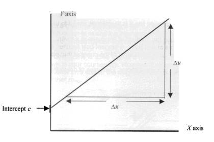
The general form of a linear equation is y = mx + c in which y is taken to be the dependent and x the independent variable; this is the one that you vary, with m and c being constants The gradient of the line, which may be negative, gives the value of m whilst the intercept on the vertical axis gives the value of c.
A graph is used to summarise data in a pictorial way such that the main features of the relationship under investigation can be seen Since linear relationships are easier to 'see' the straight line graph is of great importance in physics.
Plotting graphs
In order to extract the maximum of reliable data from a graph it is important to make full use of the graph paper,
a. Whenever it is available make use of 1 mm A4 graph paper but in all case use A4 graph paper
b. When choosing a scale for the graph ensure your data covers at least 8cm by 8cm on that scale
c. When finding the gradient make sure that you use the largest possible values for D x and D y
d. Include error bars and / or least and greatest gradient lines
e. Do not forget the units for m and c
The intercept
For an equation of the form y = mx + c when x = 0 then y must be equal to c
WARNING!
If the x-axis does not start at x = 0 then the intercept on the y-axis WILL NOT give the value of c
Sometimes in order to generate a more sensible scale it is better not to start at x = 0 but the above warning must then be remembered. The y-axis does not, however, need to start at y = 0 in order to obtain the value of c from the intercept.
The gradient
If we consider the equation y = mx + c then we can transpose to give,
m = y
- c
x
You should also notice that the gradient is given by
gradient =
change in y value
change in x value
OR
gradient = D
y
D x
Relationships involving powers
Not all of the relationships you investigate will be linear in nature,
many will be of the form y = kxn where k and n are constants.
Plotting a graph of y and x would produce a curve which would not allow k or n
to be found. This can be resolved be the use of logs.
y = kXn
log y = log k
+ nlog x
or
log y = nlog x + log k
this is now
y =
mx +c
If you now plot log y on the vertical axis and log x on the horizontal a
straight line will be produced which will allow n to be found from the gradient
and log k to be found from the intercept. This, in turn, allows k to be found.
When you plot a log graph the log values need to be tabulated; note that log
values do not have units.
|
P.D. (V) |
log(P.D / V)* |
current (A) |
log(current / A)* |
|
|
20.0 |
1.30 |
0.60 |
-0.22** |
|
|
40.0 |
1.60 |
1.6 |
0.20 |
|
|
60.0 |
1.78 |
3.3 |
0.52 |
|
|
80.0 |
1.90 |
4.9 |
0.69 |
|
|
100 |
2.00 |
6.5 |
0.81 |
|
*
use a sensible number of significant figures - you have got to plot the
data later.
** take care - log values can be negative
Rather
than draw a log graph to turn a curve into a straight line it is sometimes
useful to use a curve in order to more readily see the trend of the results
Information is sometimes required that means finding the gradient of the curve
at a given point. This is done by drawing a tangent to the curve at that paint A
tangent only touches the curve at that one point and is said to be
'perpendicular to the normal of the curve at that point'
It
is probably easiest to draw a tangent with the aid of a small mirror Two ways of
doing this are shown below.
Drawing
tangents is often utilised in work involving varying rates.
 |
Rotate the mirror until the curve and the reflection are continuous. Drawing along the mirror will give the normal and a protractor can be used to draw the tangent |
|
Position the mirror such that the curve and its image are symmetrical. Drawing along the minor gives the tangent
|
Dealing with
Errors when Using Graphs
When
a graph of the form y = mx + c is plotted it produces a straight line The
gradient of such a graph is m and the intercept c. These values are often the
quantities we are trying to find in our investigation and as such some
estimation of the error in them needs to be made.
The
best fit line is used to give a measurement of the gradient and intercept. This
must be shown in your coursework However if we wish to estimate the error then
we can draw the two additional lines shown the diagram. The gradient of the
steeper of the two is called mmax and the other mmin.
The error in the value of m can be estimated as
m max
- m min
= Dm
2
therefore
the value quoted for the gradient is;
Dc
= c max -
c min
2
hence this value is recorded as c ± D c
Obviously
you need to keep a careful eye on the number of significant figures used and
also try to make sure that you don't include any points which are known to be in
error. If a point seems to be too far away from the trend shown by the others
either go back and check it or consider leaving it out. If you leave it out of
your graph you should still record it in your results table and comment on why
you have omitted it from the graph
The
values for the quantities on the x and y axes will have an error associated with
them and this can be shown on the graph by the use of error bars. Rather than
simply plotting a point lines are added to show the error range
Whilst
the use of appropriate ICT, graphical calculators, spreadsheets
graph‑drawing software etc., is to be encouraged the following need to be
borne in mind
There must be clear evidence, in the form of a graph with a suitable grid, of plotted points
The scale chosen must be appropriate to the task
A properly judged best fit line must be shown
A suitable large triangle needs to be shown on your graph when the gradient is to be determined
The use of the best fit line must be clear in any determination of gradient and/or intercept
The scatter of points about your best fit line may be used to indicate reliability
The
use of linear regression will, generate a second value for the gradient and
/ or intercept in addition to quantifying the scatter of points.